nnfc.cense@iisc.ac.in   |    +91-80-22933319

Deposition

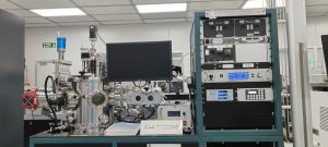
AJA Sputter Coater

Sputtering is one of the most widely used techniques for depositing thin films. The target is a plate of the materials to be deposited or the material from which a film is synthesized. Because it is connected to the negative terminal of a dc or RF power supply, the target is also known as the cathode. Typically, several kilovolts are applied to it. The substrate that faces the cathode may be grounded, electrically floating, biased positively or negatively, heated, cooled, or some combination of these. After evacuation of the chamber, a gas, typically argon, is introduced and
serves as the medium in which a discharge is initiated and sustained. Gas pressures usually range from a few to 100mtorr. After a visible glow discharge is maintained between the electrodes, it is observed that current flows and that a film condenses on the substrate. In vacuum, of course, there is no current flow and no film deposition. Microscopically, positive ions in the discharge strike the cathode plate and eject neutral target atoms through momentum transfer. These atoms enter and pass through the discharge region to eventually deposit on the growing film. In addition, other particles (secondary electrons, desorbed gases, and negative ions) as well as radiation (X-rays and photons) are emitted from the target. The deposition of Nb, Al, NbTi and Ta and its nitrides can be executed in this tool.

Sputtering system supplied by AJA International, Inc.
DC sputtering and DC and RF Biasing are feasible
Edwards Dry pump XDS 35i for low vacuum with a speed of 35 m³/hr
Cryo Torr 8 pump for high vacuum and its ultimate vacuum 5×10⁻⁹ Torr
Pirani and Hot cathode gauges for chamber
Three magnetrons of 2” and One magnetron of 3” is use
1 circular substrate holder of 4” diameter
Substrate heating up to 600 deg C
Target dimensions – 3”/2” dia and ≤ 6mm thickness

This section will be updated soon.

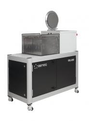
Atomic Layer Deposition_Beneq

ALD process is based on surface controlled thin film deposition. During coating, two or more chemical vapours or gaseous precursors react sequentially on the substrate surface, producing an amorphous solid thin film. ALD is an enabling technology offers precise control of the film thickness, at true nanometer scale. Pinhole free films for e.g., superior barriers, insulators and surface passivation.  Accurate and Conformal coating on large area substrates and complex 3D objects, including porous bulk materials.

TFS 200 is an Atomic Layer Deposition (ALD) system from BENEQ, Finland. It belongs to the group of chemical vapour deposition methods.

Process Capability

  • Al2O3 Deposition: Trimethylaluminum (TMA) + Deionized (DI) Water (H2O)
    • 17 ± 1.5 nm Al2O3 in 134 Cycle at 250°C
    • Average Thickness Measured: 16.83 nm
    • Average Refractive Index Measured: 1.67 at 632 nm
  • TiO2 Deposition: Titanium Isopropoxide + Deionized (DI) Water (H2O)
  • Al2O3 Deposition: TMA + Ozone process is being optimized.


Tool Capability

Substrate temperature range: 25 – 500 °C

Single wafer: Ø 200 × 3 (mm)

Gas lines: up to 8

Liquid sources (+5 °C to ambient): up to 4, currently available TMA for Al.

Hot source HS 300 (ambient to 300 °C): up to 4, currently available for Ti iso-propoxide.

Hot source HS 500 (ambient to 500 °C): upto 2 , can be used for HfO2( not available).

Control system: PLC control with PC user interface


This section will be updated soon.

Drive-In and Annealing Furnaces

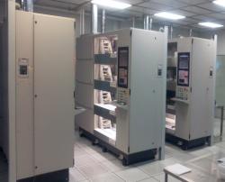
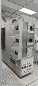
Two stacked furnace dedicated for processing twenty five 4 “wafers simultaneously and temperatures upto 1150 deg C.

Process Capability

Tube 3 Drive in: Drive-in after doping (Level 1, MOS clean). Wafers should come from Level 1 wet benches only after mandatory RCA clean carried out just before furnace entry.

Tube 4 Annealing: metal contact annealing (Al,Ti,W)


Tool Capability

Tube 3 Drive in: Gases available for drive-in are Ar, N2 and O2

Tube 4 Annealing: Gases available for drive-in are H2 ,O2 And N2

This section will be updated soon.

E-Beam Evaporator (LEYBOLD)

Electron-beam evaporation, uses a focused beam of electrons to heat the metal for deposition. A controlled deposition of thin-films is achieved. The material is kept in a water-cooled crucible and exposed to the electron beam, causing it to vaporize and condense on the wafers / samples. Planetary substrate rotation provides uniform deposition. Radiant heaters are provided for substrate heating. Option for Ion Assisted deposition, Co-deposition and Ion Etching is also available.

There is one electron gun and one Ion gun.
EB gun has 1 hearth. Hearth associated with EB gun has six 20 cc pockets
Max Power 10kW Accelerating Voltage 10 kV
Beam deflection 270deg
Emission Current 0-1A
Programmable sweep controller
Substrate holder {4, 3, 2-inch diameter}
Uniaxial rotation with one holder
Genius Controller Module for E-Beam control
Ultimate Pressure ~2E-7 Torr
Process Control using Univex software
Deposition rates from 1 Å/sec to 100 Å/sec

This section will be updated soon.

E-beam Evaporator (TECPORT)

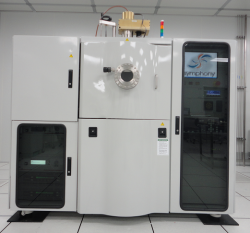
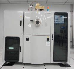
Electron-beam evaporation, uses a focused beam of electrons to heat the metal for deposition. A controlled deposition of thin-films is achieved. Both dielectrics and metals can be deposited using solid sources. The material is kept in a water-cooled crucible and exposed to the electron beam, causing it to vaporize and condense on the wafers / samples. Planetary substrate rotation provides uniform deposition. Radiant heaters are provided for substrate heating. Option for Ion Assisted deposition, Co-deposition and Ion Etching is also available.

Process Capability

Process Capability


Tool Capability

•      E-Beam evaporation is sourced from Tecport.

•       There are two electron guns and an Ion gun.

•      EB guns has two hearths. Hearth associated with EB gun-1 has four 25 cc pockets and the one associated with EB gun-2 has six 15 cc pockets.

•       One 4 pocket hearth and one 6 pocket hearth.

•       Pop-Top source

•       Max Power 10kW

•       Accelerating Voltage 4-8 kV

•       Beam deflection 270deg

•       Emission Current 0-1.5A

•       Programmable sweep controller.

•       Temescal Crucible indexer.

•       Substrate holder {6, 4, 3, 2 inch diameter}.

•       Planetary rotation with four holders.

•       Inficon IC6 deposition controller.

•       Ultimate Pressure ~2E-7 Torr.

•       Process Control using Symphony software.

•       Deposition rates from 1 Å/s to 199 Å/s.

•      Ion-assisted deposition is also possible.

This section will be updated soon.

Epitaxial Silicon CVD

Epitaxial CVD furnace capable of single wafer processing with sample sizes ranging from 2inch, 3inch and 4 inch wafers. Epitaxial and Selective Epitaxial deposition of undoped and P-doped Silicon is available.

Maximum Temperature: 1200degC
Pressure range: 6Torr to 60Torr Precursors: Dichlorosilane, Silane, Diborane, Phosphine, Germanium, Hydrogen and
Nitrogen.

This section will be updated soon.

ICPCVD_Oxford

Inductive couple Plasma chemical Vapor Deposition is a process where high density plasmas is created with the ICP source. This technique delivers deposition of high qualitydielectric films at low temperature with low damage. Low temperature deposition means that temperature sensitive films and devices can be processed successfully

This section will be updated soon.

Process Capability

Materials Deposited:

§Dielectrics : SiO2, SiNx, SiOxNy,
§SiO2 Trench Filling

Sample Size: Small cut Piece to full 6”inch full wafer

Samples Materials

§Allowed: Silicon, quarts, sapphire
§Not allowed: PET, Kepton, Photoresist, Soda lime glass


Tool Capability

Tool Spec


Substrate temp range (DegC) :  0 to 350

2 Temperature Mode:

Chiller Mode  < 80degC > Heater Mode


Pressure : (5 to 80) mTorr


RF power : 2MHz, 600W

ICP power : 13.56MHz, 3kW


Gas Flows:

Carrier Gas: PN2, Ar

Precursors Gas : NH3, SF6, O2, SiH4, N2O

This section will be updated soon.

Low Pressur CVD

Four stacked furnace capable of processing twenty five 4 inch wafers simultaneously at temperatures upto 950 deg C and low pressures of upto 500 millitorr.

Process Capability

Tube 1 (Silicon Nitride):

Tube 2 (Doped polysilicon and silicon germanium)

Tube 3 (Undoped polysilicon and silicon germanium)

Tube 4 (Low temperature oxide)

  • High and Low Temperature PSG and BPSG Oxide using Oxygen, Nitrogen, Silane, TEOS bubbler, 1% Diborane/Argon and 1% Phosphine/Argon at temperatures up to 950 Celsius (Please note that currently only LTO is available which uses silane and oxygen)
  • LPCVD Tube 4 LTO


Tool Capability

  • Tube 1, Silicon nitride deposition: MOS Clean, High stress (>1GPa) and low stress (~100 MPa) nitride films
  • Tube 2, Polysilicon/PolyGe/SiGe deposition: Metal contaminated, Level 3, amorphous and poly Si, Ge and Si-Ge deposition
  • Tube 3, Polysilicon/PolyGe/SiGe deposition: MOS clean, amorphous and poly Si, Ge and Si-Ge deposition
  • Tube 4, LTO, TEOS, BPSG, PSG deposition: MOS clean, Level 3, Low temperature SiO2, TEOS oxide, Boron and phosphorus doped oxide

This section will be updated soon.

Oxidation and Diffusion Furnaces

First Nano oxidation and diffusion furnaces for oxidation and dopant diffusion. These are MOS clean and wafers processed here should never have gone through a metal deposition step, even if the metal has been removed.

Process Capability

Tube 1 Oxide grown in the range of 5-150 nm

Tube 2 Oxide grown in the range of 300- 1000 nm

Tube 3 Phosphorus diffusion using POCl3

Tube 4 Boron diffusion using Diborane.

First_nano_Furnace_-Oxdn__and_diffusion_timings


Tool Capability

Capable of processing twenty five 4 “ wafers simultaneously and temperatures upto 1150 deg C. Wafers should come from Level 0 / 1 wet benches only.

Tube 1 (Dry oxidation furnace):

  • Has a lower rate of oxide growth, but a better film quality
  • Used for making thin oxides and silicon oxynitride
  • Gases available are oxygen, nitrous oxide and nitrogen
  • Temperatures up to 1150 deg C

Tube 2 (Pyrogenic furnace):

  • Uses pure steam for oxidation
  • Has a significantly higher rate of growth compared to dry oxidation
  • Used for making thicker oxides like field oxide
  • Gases available are Oxygen, Hydrogen and Nitrogen
  • Temperatures up to 1150 deg C

Tube 3 (Phosphorus diffusion furnace):

  • Uses POCl3 bubbler for doping
  • Gases available are oxygen and nitrogen
  • Temperatures up to 1150 deg C

Tube 4 (Boron diffusion furnace):

  • Uses diborane as the gaseous source
  • Gases available are diborane (1% in Ar), oxygen and nitrogen
  • Temperatures up to 1150 deg C

This section will be updated soon.

PECVD_ Oxford (OI)

Plasma Enhanced Chemical Vapour Deposition (PECVD) utilizes plasma to enhance the reaction of the precursors. It is a low temperature process when compared to conventional Chemical Vapour Deposition (CVD). It uses RF energy to generate plasma where the deposition can be done below 380C. The deposited material will be conformal in nature. The deposition rate is high compared to conventional CVD. The deposited material can have smooth surface. The deposited material will always be amorphous in nature.

Process Capability

•       Substrate size: Deposition can be done on wide variety of sample (i.e., even polymer samples, glass samples and silicon substrates, small cut pieces to 8” wafer).

•       Multiple depositions can be done like stack deposition.

•       Dielectric materials like SiOx, SiNx, SiOxNy, GeOx.

•       Semiconductor materials like a-Si, Ge, SiGe can be deposited.

•       Phosphorus and boron doped oxide films can be deposited.

•       Stoichiometry of the deposited material can be controlled.

•       Film stress can be controlled by high/low frequency mixing techniques


Tool Capability

  • Maximum deposition temperature : 3800C
  • Minimum deposition temperature : 1000C
  • High Frequency RF Generator:13.56 MHz ,600W
  • Low Frequency RF Generator: 350KHz-500W
  • Top electrode :RF driven (MHz and/or kHz).
  • Bottom Electrode: No RF Bias ( substrate).
  • Gases used are H2, SiH4, GeH4, CH4, NH3, CF4, N20, N2, Ar, 2%B2H6/Ar, 1%PH3/Ar.
  • Wafers or carrier plate up to 150mm dia.

This section will be updated soon.

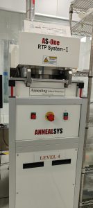
Rapid Thermal Anneal Sys1

RTP system which heats silicon wafers to high temperatures (up to 1100 °C ) on a timescale of several seconds or less. During cooling, however, wafer temperatures must be brought down slowly to prevent dislocations and wafer breakage due to thermal shock, Available gases N2,Ar,O2 AndH2

It can used for Annealing Contact Alloying, Rapid Thermal Oxidation (RTO), Rapid Thermal Nitridation (RTN),Densification and Crystallization, Silicidation etc.

Process Capability


Tool Capability

  • Sample Size from Small pieces to a single4 ” full wafer
  • Temperatures up to 1100 deg C
  • Ramp rates from 20 deg C/s to 200 deg C/s

This section will be updated soon.

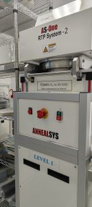
Rapid Thermal Anneal Sys2

System for oxidation and oxy-nitridation carrying gases O2, N2, N2O and Ar. This is a MOS clean system and wafers processed here should never have gone through a metal deposition step, even if the metal has been removed. Wafers should come from Level 0 / 1 wet benches only.

Process Capability

Oxide and oxynitride thicknesses up to 20nm


Tool Capability

  • Sample Size from Small pieces to a single 6” full wafer
  • Temperatures up to 1100 deg C
  • Ramp rates from 20 deg C/s to 200 deg C/s

This section will be updated soon.

Sputter Coater1 Metals_Tecport

Sputtering is one of the most widely used techniques for depositing thin films. The target is a plate of the materials to be deposited or the material from which a film is synthesized. Because it is connected to the negative terminal of a dc or RF power supply, the target is also known as the cathode. Typically, several kilovolts are applied to it. The substrate that faces the cathode may be grounded, electrically floating, biased positively or negatively, heated, cooled, or some combination of these. After evacuation of the chamber, a gas, typically argon, is introduced and serves as the medium in which a discharge is initiated and sustained. Gas pressures usually range from a few to 100mtorr. After a visible glow discharge is maintained between the electrodes, it is observed that current flows and that a film condenses on the substrate. In vacuum, of course, there is no current flow and no film deposition. Microscopically, positive ions in the discharge strike the cathode plate and eject neutral target atoms through momentum transfer. These atoms enter and pass through the discharge region to eventually deposit on the growing film. In addition, other particles (secondary electrons, desorbed gases, and negative ions) as well as radiation (X-rays and photons) are emitted from the target.

Process Capability

  • 4 circular substrate holders of 6” diameter.
  • Coating uniformity up to 4” substrate size with rotation. uniformity upto 1.5″ circular area for stationary deposition.
  • Target dimensions – 3” dia and ≤ 6mm thickness.
  • Substrate heating up to 600 deg C using localized heaters.
  • Substrate planetary rotation is available for better film uniformity.
  • Cu, Fe, Selenium and Zn targets are not allowed.
  • Target_list_sputter 1


Tool Capability

  • Sputtering system supplied by Tecport, one for metals
  • DC sputtering, RF sputtering and Reactive sputtering are feasible.
  • Rotary Dry pump with a pumping speed of 1670 lit/min
  • Turbo Molecular pump for high vacuum with a speed of 1450 lit/sec, 31500 rev/min and its ultimate vacuum 8×10⁻⁸ T
  • Pirani, Penning, Full range and Baratron Gauges for chamber.
  • Three magnetrons in each unit– DC and RF power sources in sputter-1
  • DC and RF bias is possible

This section will be updated soon.

Sputter Coater2 Dielec_Tecport

Sputtering is one of the most widely used techniques for depositing thin films. The target is a plate of the materials to be deposited or the material from which a film is synthesized. Because it is connected to the negative terminal of a dc or RF power supply, the target is also known as the cathode. Typically, several kilovolts are applied to it. The substrate that faces the cathode may be grounded, electrically floating, biased positively or negatively, heated, cooled, or some combination of these. After evacuation of the chamber, a gas, typically argon, is introduced and serves as the medium in which a discharge is initiated and sustained. Gas pressures usually range from a few to 100mtorr. After a visible glow discharge is maintained between the electrodes, it is observed that current flows and that a film condenses on the substrate. In vacuum, of course, there is no current flow and no film deposition. Microscopically, positive ions in the discharge strike the cathode plate and eject neutral target atoms through momentum transfer. These atoms enter and pass through the discharge region to eventually deposit on the growing film. In addition, other particles (secondary electrons, desorbed gases, and negative ions) as well as radiation (X-rays and photons) are emitted from the target.

Process Capability

  • 4 circular substrate holders of 6” diameter.
  • Coating uniformity up to 3” substrate size with rotation. uniformity upto 1″ circular area for stationary deposition.
  • Target dimensions – 3” dia and ≤ 6mm thickness.
  • Substrate heating up to 600 deg C using localized heaters.
  • Substrate planetary rotation is available for better film uniformity.
  • Using halogen lamp can heat the sample up to 100oC
  • Using 3 position gate valve vary the deposition pressure from 8e-4 to 5e-2 T
  • Target_list_sputter 2


Tool Capability

  • Sputtering system supplied by Tecport, for dielectrics
  • DC sputtering, RF sputtering and Reactive sputtering are feasible.
  • Rotary Dry pump with a pumping speed of 1670 lit/min
  • Turbo Molecular pump for high vacuum with a speed of 1450 lit/sec, 31500 rev/min and its ultimate vacuum 8×10⁻⁸ T
  • Pirani, Penning, Full range and Baratron Gauges for chamber.
  • Three magnetrons in each unit– DC and RF in power sources sputter-2
  • RF bias is possible

This section will be updated soon.

Tempress Annealing System

Tempress Three Stacked Furnace dedicated for dielectric annealing and Oxidation, at the temperatures ranges between (350°C to1000°C). The process is carried out at atmospheric pressures.

This section will be updated soon.

Process Capability


Tool Capability


This section will be updated soon.